High-concerned chemical : none
Type : Module
Brand Name : DIY NOW
Origin : Mainland China
Condition : New
Power supply requirements: : Voltage: 12V/DC, current above 100mA
PCB size: : 9.5X5.8 cm
1 Supported models: : Single op amp models: LM741, LF356, NE5534, TL071,
2 Supported models: : Dual op amp models: LM358, NE5532, TL072, TL082, M
3 Supported models: : Quad op amp models: LM324, TL074, TL084, LF347, AD
Product features:
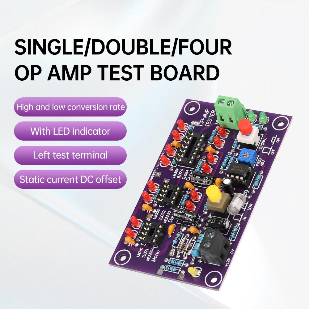
1. This operational amplifier test board can be used to test common single op amp, dual op amp, quad op amp chips, and distinguish high speed and low speed of finished boards.
2. This circuit board can determine whether 1C can be used for amplification, and can also determine the conversion rate of the chip.
3. This T2 operational amplifier test board can find low-speed chips that pretend to be high-speed chips.
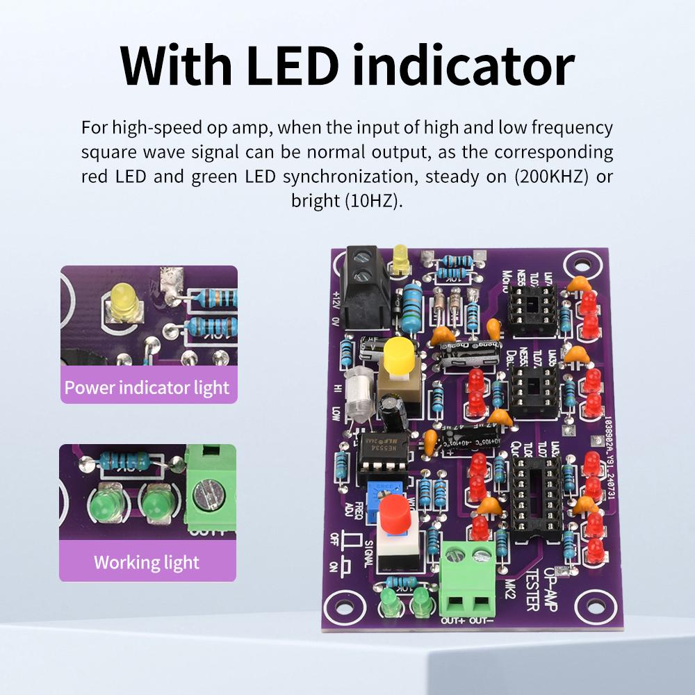
4. With LED indicator light, for high-speed op amps, both high- and low-frequency square wave signals can be output normally when input, which is manifested as the corresponding red LED and green LED are synchronized, always on (200KHZ) or flashing (10HZ).
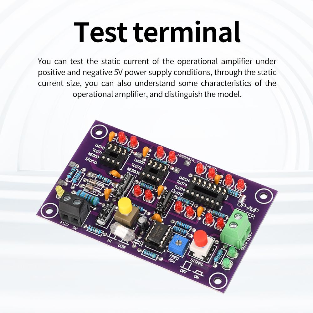
5. There are test terminals on the board, which can test the static current of the operational amplifier under the conditions of positive and negative 5V power supply. Through the size of the static current, some characteristics of the op amp can also be understood, and the model can be distinguished at the same time.
Test principle:
The signal source generates a high-frequency square wave with a frequency of 200KHZ and a low-frequency square wave with a frequency of about 10HZ. The tested op amp is connected to a buffer circuit.
For high-speed op amps, both high- and low-frequency square wave signals can be output normally, which is manifested by the corresponding red LED being synchronized with the green LED, and being always on (200KHZ) or flashing (10HZ).
For low-speed op amps, when high-frequency square wave signals are input, the output end cannot output the waveform completely, which is manifested by the corresponding red LED not being able to light up normally, only one or both being lit. Only when low-frequency signals are input, the output can be normal, and the corresponding red LED at the output end can flash synchronously with the green LED.
There are test terminals on the board to test the quiescent current of the operational amplifier under positive and negative 5V power supply conditions. Through the size of the quiescent current, some characteristics of the op amp can also be understood, and the model can be distinguished at the same time.
Product parameters:
Power supply requirements: Voltage: 12V/DC, current above 100mA
PCB size: 9.5X5.8 cm
Supported models:
Single op amp models: LM741, LF356, NE5534, TL071, TL081, OP07 and other standard packaged single op amps.
Dual op amp models: LM358, NE5532, TL072, TL082, MC1458, RC4558, 0P275, AD827 and other standard packaged dual op amps.
Quad op amp models: LM324, TL074, TL084, LF347, AD713, etc.
Test notes:
1. Only one chip can be tested at a time, and only one of the three test sockets can be used.
2. For the test of static current, you need to use the DC voltmeter of a digital multimeter to test the voltage across 10 ohms, I=V/10(ma), for example, V=15MV, then the static current I=1.5 ma. (At this time, there is no need to press the red switch on the right side of the picture).
3. The test end can be connected to an oscilloscope or frequency meter, and the potentiometer can be adjusted to change the test frequency.
label:yes






 Zwrot w przypadku braku dostawy